ICCAD 2017 Contest
Input Sequence Generator for SystemVerilog Assertion Checking
Chun-Ming Huang and Wei-Chang Tsai
國家晶片系統設計中心 (CIC), Taiwan
0. Announcements
- Beta test result announcement - 2017/08/14
- FAQ updated - 2017/07/25
- FAQ updated - 2017/07/21
- FAQ updated - 2017/07/17
- FAQ updated - 2017/07/10
- Alpha test result announcement - 2017/07/04
- FAQ updated - 2017/06/27
- FAQ updated - 2017/06/22
- FAQ updated - 2017/06/12
- FAQ updated - 2017/06/09
- FAQ updated - 2017/06/06
- FAQ updated - 2017/06/02
- FAQ updated - 2017/05/03
- New Benchmarks released. - 2017/04/27
- FAQ updated - 2017/04/25
I. INTRODUCTION
Assertions may be used to verify the behavior of a design. They use a concise description to describe the complex behavior or the specification of a hardware system. Assertions can be checked dynamically by a simulator or statically by a property checking tool. These tools can check whether the design meets the specification or the properties described in the assertion rules.
In SystemVerilog, there are two kinds of assertions: immediate (assert) and concurrent (assert property). The immediate assertions are procedural statements and are mainly used in simulation. A conditional expression is evaluated immediately in the assertion. If the evaluated value is X, Z, or 0, then the assertion fails and the simulator outputs an error message. The concurrent assertion rules are the statements that assert the specified properties. The conditional expression is evaluated throughout simulation. They can be checked at every point in the simulation. They can also be checked on a rising or falling edge of a clock signal.
II. Problem Description
In this problem, a finite state machine and some concurrent assertion rules are given. Please write a program to generate an input sequence for the finite state machine, such that the input sequence makes the assertions failed during simulation. The finite state machine and assertion rules are implemented by SystemVerilog. The module name of the finite state machine is fsm. A test bench is given to verify the input sequence. Please note that the input sequence may not exist to make some assertions failed. Several benchmarks will be given to evaluate your program.
III. Goal
The goal is to develop an input sequence generator program to find an input sequence that makes the given assertions failed. Try to make the input sequence as short as possible and make the number of failed assertions as large as possible. An evaluation set consisting of several benchmarks is provided for evaluating your program. For each benchmark, your program must generate the input sequence and make the maximum number of assertions failed. An assertion failing many times is counted only once. Runtime spent for each benchmark will be also used for grading your work. You will have a better grade if the runtime is less.
IV. Terminology
Assertion rule:
The assertions can be implemented by SystemVerilog using the following example statement:
assertion_rule1: assert property
(@(posedge clk) $rose(req)|->##[1:3] $rose(ack))
else $display(“assertion rule1 failed”);
As shown in Figure 1, this assertion rule can be used to check whether the acknowledge signal comes within 1 to 3 cycles delay after the request signal req is asserted. The assertion will fail and show the error message if the acknowledge signal ack comes after more than 3 cycles .

Fig.1 Timing diagram of the req and ack signals.
V. Input Format
The input file is a SystemVerilog netlist. In this file, the behavior of the finite state machine is described in a module named fsm, and the assertions are also given in the fsm module. There is also a module named test used for reading the input sequence for verifying the assertions during simulation.
5.1. Finite state machine Verilog model
The Verilog model is used to describe the behavior of the given finite state machine. Note that there is more than one assertion in the Verilog model. An example is shown as follows:

Fig.2 An example of finite state machine Verilog model.
5.2. The assertion rules
The assertion rules are all concurrent assertion rules and checked at positive edge of clk. The signal is 1-bit input or output signal and can be evaluated by $rose or $fell function. For example, $rose(in[1]) is true if in[1] is changed to 1. The $fell(in[1]) function is true if in[1] is changed to 0. The symbol of “##” is the delay operator. The range after the delay operation may be changed in each rule.
VI. Output Format
TThe output of your program is a file containing the sequence of input patterns for the finite state machine. The output format is described as follows: Each line shows an input pattern. In each line, the first digit is the value of the rst signal and the remaining digits are the values of the inputs from the msb (most significant bit) to the lsb (less significant bit). The following is an output example for the finite state machine in Figure 2. The order of signal names is rst, in[1], and in[0].
000
100
010
011
…
The output file is used to verify the assertions. The input patterns will be read one by one into the test bench for simulation. In order to make this contest fair, the rst signal must be enabled (from logic 0 to logic 1) for entering the start state at the beginning of input sequence. However, you can also re-enable the rst signal to force the finite state machine to enter the start state in the any part of the input sequence.
VII. Example
We use a small finite state machine in Figure 3 as an example to illustrate the assertion failed. The following is an example of the assertion rule. The output signal must be active after 1 to 3 cylces when the input signal in[1] is active.
assertion_rule1: assert property
(@(posedge clk) $rose(in[1])|->##[1:3] $rose(out))
else $display(“assertion rule1 failed”);
If the example of input sequences as shown in Figure 4 and Figure 5 are used for simulation, the above assertion will failed and show the failed message.

Fig.3 State diagram of an example finite state machine.

Fig.4 The example input sequence #1.

Fig.5 The example input sequence #2.
The input sequence can be verified by SystemVerilog. The first command is compile the designs:
vcs –sverilog fsm.v test.v
The second command is used to run the simulation:
./simv
The output message of simulator will show the assertion is failed if you active the assertion and failed.
"fsm.sv", 33: test.f1.assertion_rule1: started at 70s failed at 130s
Offending '$rose(out)'
VIII. Evaluation
You have to guarantee the correctness of program compiling and running. The compiled executable should be stored in the root directory of your deliverables. Under the command prompt, key in “time your_program_name –i fsm.v –o input_sequence” and press enter. Your program should create an output file named input_sequence that contains the generated input sequence. Then, the file can be simulated by SystemVerilog to check the number of failed assertions.
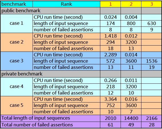
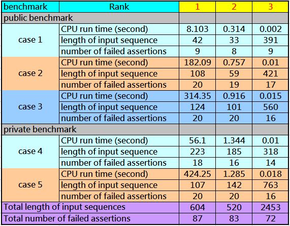
2. Performance evaluation
The performance metric is the total number of failed assertions found for all benchmarks/cases including the public and hidden benchmarks. A team that finds more failed assertions will get a higher score. However, if two teams find the same number of failed assertions, the team that generates a shorter input sequence will get a higher score. If the lengths of the input sequences are also the same, the team that spends less runtime will gets a higher score. Basically we will terminate the test if a program runs over 2 hours. Your program does not need to follow the order of the given assertions. You can change the order for the optimization of the input sequence length.
IX. Reference
- Verilog Parser
- Icarus is a free Verilog simulation and synthesis tool. The source codes are available at
http://iverilog.icarus.com/ - VBS is another free Verilog behavioral simulator. The source codes are available at
https://code.google.com/archive/p/verilog-behavioral-simulator/
- Icarus is a free Verilog simulation and synthesis tool. The source codes are available at
- Verilog format
X. TestCase
XI. Alpha Test
XII. Beta Test
XIII. FAQ
-
想請問這題裡面fsm.v跟test.v的檔案是否會給呢? 因為要寫input_sequence需要判斷fsm.v裡面的assertions,所以如果沒有fsm.v將沒有辦法判斷,還是我們需要自己去判斷將來寫進來的fsm.v裡面的語句呢??而且在網頁上也沒有看到下載的連結。
fsm.v 和 test.v 將會放在測資裡,一併於4月底提供。 -
D題在problem description提到,a finite state machine and some concurrent assertion rules are given,但是terminology之後都以example說明,並沒有提到真正競賽的assertion rules到底有哪些,所以才會覺得題目給的條件不足以做出project,希望能得到更多題目資訊或是測資。還是這題的用意就是要我們去猜他的rules有哪些呢?
Assertion rules 包含在測資裡的 fsm.v 裡。 -
請問範例中input的[1:0] in只有2bits,請問在之後測試的資料裡面還是2bits的input嗎?還是有可能更多或更少?
測資的輸入與輸出位元數將都不同,不會是只有2位元的輸入或輸出。 -
請問範例提供的finite state machine是之後都會使用這個state machine,還是之後的state machine會不一樣?
測資的Finite state machine(FSM) 將是不同於範例的FSM。 -
請問assertion rules會給在側資裡面? 還是不會給我們知道,而我們只能透過input sequences去測試,最後只看的到測試結果?
assertion rule 將會放在測資裡面, 提供給參賽者。 -
Performance evaluation 提到的public and hidden benchmark的形式是什麼樣子? 另外,這裡的hidden和public是什麼意思呢?
測資分成兩類,一類公開提供參賽者使用,另一類不公開, 評分時會加上不公開的分數,避免參賽者只針對公開的測資作最佳化。 -
請問在assertion rules這些被拿當規則的變數(in、out)是否有數目上的限制? 舉例來說,一個assertion rules有可能條件這麼長的情況嗎:
$rose(in[1])|->##[1:3] $rose(out)|->##[1:3] $rose(in[0])|->##[1:3] $fell(in[1])|->##[1:3] $fell(out),
還是跟範例一樣限制在2個in和out的signal:
$rose(in[1])|->##[1:3] $rose(out)
為簡化題目,只限制成兩個訊號, 可能一個輸入,一個輸出訊號,也可能是兩個輸入訊號或兩個都是輸出訊號。 -
能否提供其他的assertion_rules做為參考?
將會於測資中提供。 -
想請問 在題目中 assertion rule假如是長這樣,@(poseedge clk) rose(in[1])|->##[1:3]$rose(out[0]),那我要讓他fail是除了我in[1]要rose以外,我也要考慮是否會讓out[0]rose嗎?還是說我如果出來的sequence是超過delay time它自動會fail?
這個assertion rule 是指當in[1] 為 rose 後開始檢查,所以要先讓in[1] 由 0變成1,並產生一組輸入讓 out[0] 在之後1~3 個週期內不會由0變成1,就會產生fail,當然如果都沒有變化,也會fail。 -
在題目中 assertion rule假如是長這樣,@(poseedge clk) rose(in[1])|->##[10:15]$rose(out[0]),在in[1] 為 rose 以後的第9個週期,如果in[1]又重新rose了,請問這條rule的週期會從第10個週期開始重新計算嗎? 或是第一次滿足in[1]為 rose和第二次滿足in[1] 為 rose 會分別計算週期呢?
Assertion rule 檢查是並行的,in[1] 第一次由0變成1時,會持續於之後的10~15個週期檢查out[0],in[1]第二次由0變成1時,會持續於此次變化之後的10~15個週期檢查out[0], 分開檢查,不會互相影響。 -
assertion rule假如是長這樣,@(poseedge clk) rose(in[1])|->##[1:3]$rose(out[0]),根據題目敘述,當in[1] 由0變1後,在1至3個cycle間,若out[0]沒有由0變1,則代表該assertion fail。但若在這1至3個cycle間,in[1]又再次由0變1,則判斷out[0]由0變1的時間,是否要再往後延1至3個cycle?
Assertion rule 檢查是並行的,in[1] 第一次由0變成1時,會持續於之後的1~3個週期檢查out[0],檢查期間內,如果in[1]第二次由0變成1時,會持續於此次變化之後的1~3個週期檢查out[0],分開檢查,不會互相影響,所以不會省略(往後延)第一次變化的檢查。 -
請問reset有限制可以連續的次數嗎,i.e., 可以連續產生一個10個reset的input sequence?
reset 沒有連續次數的限制。 -
如果我reset的話,所有的assertion rule要重算嗎?也就是我在連續的reset之後,assertion 還是會繼續條件的delay time嗎?
assertion rule 檢查不會因為reset 而重新計算與檢查,仍會持續檢查。 -
在題目敘述的範例,請問使用reset以後的output應該參考哪一個state呢? 例如我現在在S2,連續使用reset功能兩次,確定會回到S0,那對應的output分別會是什麼?
sample input:
101
100
題目電路的reset 為正緣觸發,也就是說要由0變成1 才能進到初始狀態 S0,reset 連續為1,則不會執行reset 動作,會依據輸入的值進到FSM的下一個狀態。如果進到狀態S0時,輸出(out) 為邏輯0。 -
請問在實作上可以連續一直使用reset,試圖讓assertion rule failed嗎? 這樣會不會違反這次推廣題的精神或規則呢?
reset 正緣觸發時,狀態會回到初始狀態 S0,於找最短輸入input sequence 時,可以考慮用reset 達到最佳化,但是一直使用reset 不一定能找到最短的,input sequence,也不建議使用這樣的方式,這樣的違反出題者的本意。 -
請問在Example section裡說明的vcs及simv指令是否要安裝什麼軟體才能執行呢?可以提供該軟體讓我們測試自己的結果嗎?
vcs 與 simv 指令需要執行 Synopsys vcs 軟體,競賽給的環境應該可以直接執行,執行檔在底下目錄: /cad/synopsys/vcs/cur/bin。 -
依照題目敘述的理解,我們猜測我們程式產生的input sequence在測試時應該是 在每次clock rise時會讀進一行input,也就是input的變化是發生在每次clock rise時,請問是這樣嗎?我們查看testbench裡的test.v,發現似乎clock cycle是10,而input讀進來的間隔則是20?這樣是兩次clock rise後input才會變化嗎?那assertion的delay也就會變成2倍了?
clock cycle 是 20,因為每次 10 ns clk 才會轉換一次,20ns 才回到原來的邏輯值,故clock cycle 是20ns ,資料也是20ns 匯入一筆。 -
網站上先前的FAQ裡寫到「電路的reset是正緣觸發」,但verilog寫
always @(posedge clk or posedge rst) begin
if (rst) pstate <= S0;
else pstate <= nstate;
end
我們的理解是,如果rst一直維持在1,這個block還是會在posedge clk時執行,並且會執行if (rst)那行,也就是仍然會reset到S0。這和FAQ敘述的不一樣,讓我們很困惑。
關於reset 您們的理解是正確的,原先FAQ 提到的是針對一開始進入reset 狀態的描述,正確的做法是會將rst 設回邏輯0,finite state machine 會依據輸入與目前狀態進行動作,需要reset 時,再將rst 設成邏輯 1。 -
網站提供的TestCase - ProblemD0426.tar中的3個tb測試檔會產生fail的input是否各只有1組?
輸入訊號是由外部給定,產生rise 或 fall 變化是可以自由控制,輸出則可由外部訊號的不同進到不同的狀態,輸出跟著變化,故不只一組。 -
請問是否可提供一個測試檔是不會有fail的情況發生?
建議參賽者自行依據需要,修改test case 會比較符合自己要測試的內容,主辦單位無法提供所有參賽者客製化的 test case。 -
假設有一個input sequence的長度只夠讓一個assertion觸發,在此assertion還未fail前,simulation即結束(input sequence不夠長),請問此assertion是否認定為fail?舉例來說,有個assertion在20s時被觸發,但其需要在230s時才能夠確定fail,又若input sequence的長度只能執行100s,則此assertion是否為fail。我們使用CVS模擬似乎會認定為fail。
Input sequence 長度是由參賽者自行產生, 模擬時如果需要較長的長度,則請自行產生夠長的input sequence,目前test bench 設定是 1千萬筆,不夠時將會進行調整。 - 由於題目敘述的網頁,只有提到先比failed assertions的個數,再比input sequence的長度,最後才是run time,我們想要問大會是否會公布D題評分的量化公式? 首先比五個測資找到的failed assertions總數,較多的獲勝,如果總數相同,則比五個測資的input sequence長度總和,較少的獲勝,如果再相同則比模擬的時間總和,時間較少的獲勝。
-
這次的題目還會再提供其他的public case嗎?
不會再提供其他公開的測資。 -
去年的定題組D,有提供隱藏測資的PI、PO、GATE的數量,那這次的定題組D,會像這樣公開隱藏測資的這類數據嗎,例如state的數量、input/output 訊號的寬度?
測資資訊如下:
Input Width Output Width State Number Assertion Rule Number Public Benchmarks case1 7 7 36 10 case2 7 19 96 20 case3 8 19 116 20 Private Benchmarks case4 7 19 96 20 case5 8 19 146 20 -
我們發現vcs在模擬的時候會將don't care變0當作fell,以及don't care變成1時當作rose。 請問比賽時驗證是用vcs計算assertion fail數?如果是,可以用vcs的這個特性來找解嗎?
驗證目前是使用vcs,但是基本上電路經過reset 後,所有的don’t care 值都會變成邏輯1或邏輯0,狀態回到初始狀態,這樣找出解答會比較直接,比較快。故不建議使用don’t care的方式來找出答案。 -
我們在測試時發現在讀入第一個input之前,vcs會將in這個port的值當作是don't care,還有reset之前out也會是全don't care。我們想問大會在這時後被vcs認定觸發的assertion 如果fail會不會採計?
Assertion 觸發條件是有明確的邏輯值才會觸發(fell or rose) ,一直保持don’t care 時不會觸發,故不會有fail 的情形,未reset 前都處於don’t care 情形,目前的state 也是未知,故不建議使用don’t care的方式來找出答案。